SMILE: Single Molecule Imaging Laser Engine
Engineered by John PhilippiIntroduction
The concept of the SMILE project is to develop a low cost laser controller based on an Arduino NANO which is capable to operate four low cost, in this case JLaserTrack LDM series, lasers/drivers. All necessary information (software, hardware list, etc) can be downloaded here.User Manual
Installing the SMILE Controller
The controller has several connectors starting from the left side is the 9 V DC inlet. In the front you'll notice 5 SMA connectors corresponding from left to right, Laser 1 to the Camera Trigger to the right. On the right side is the type B mini USB connector.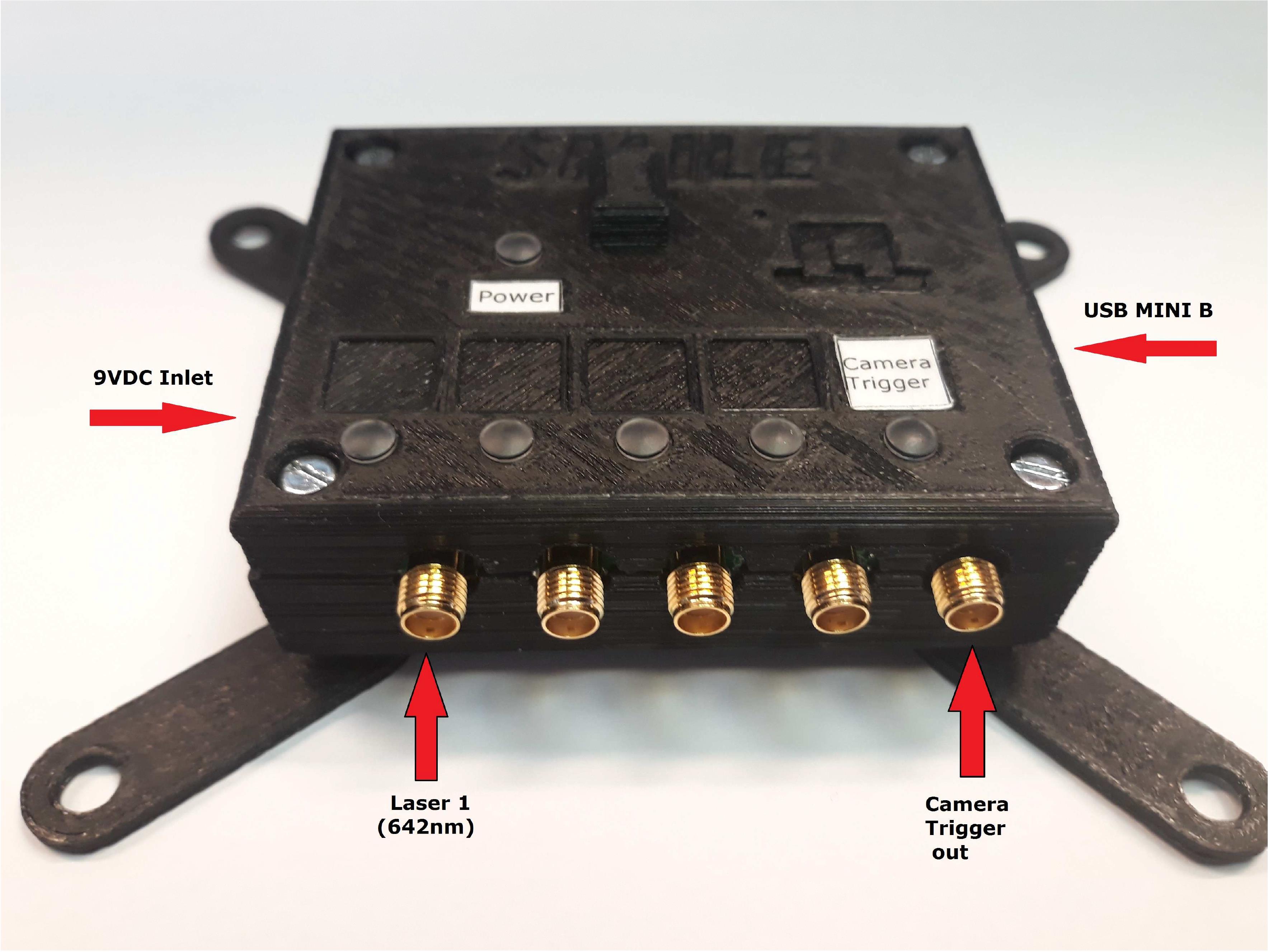
Start by connecting the lasers (trigger) and camera using the SMA connectors. Mount the controller to your optical table, if you have one, and or adjust the controller mounts to fit your table mount holes, generally inch pitch. Hook up the 9V DC mains adapter and plug it in the 9 V DC laser controller socket. The blue LED power indicator lights up.
Connect at last the laser controller USB by a USB cable connected to your computer. Windows should automatically detect the controller hardware and starts to install the correct driver. Write down the comport number the driver is attached to, you'll need it later. In case Windows does not install the driver, you can download this using the following link: http://wch.cn/download/CH341SER_ZIP.html
Installing the SMILE Graphical User Interface
The SMILE GUI needs the Labview RunTime Engine 2016 or higher to make it run. This program can be downloaded, free of charge, from National Instruments ; http://www.ni.com/download/labview-run-time-engine-2016/6067/en/Click the Installer Settings tab, click the Advanced button, then place a check mark in the Serial Port Support checkbox. This will actually install the full serial portion of the NI-VISA Runtime Engine.
Setup SMILE GUI
Unzip the SMILE.ZIP file in to your C: drive. In the SMILE directory there are four files. Use Win Notepad editor to modify the comport number in the Telegram.ini file. If you don't know the comport number, run Computer Manager in Windows, select Device Manager and open the Ports (COM & LPT) tab. Notice the USB-SERIAL driver showing the comport in brackets. Copy the Telegram.ini in the root of your C: drive.Run Smile.exe in the SMILE directory. Resize the GUI to your liking.
If you click on the Red TTL button on the left side of GUI the left laser 1 indictor light up. Using the corresponding Intensity Control slider you are able to control the intensity of the attached laser.
Using SMILE GUI
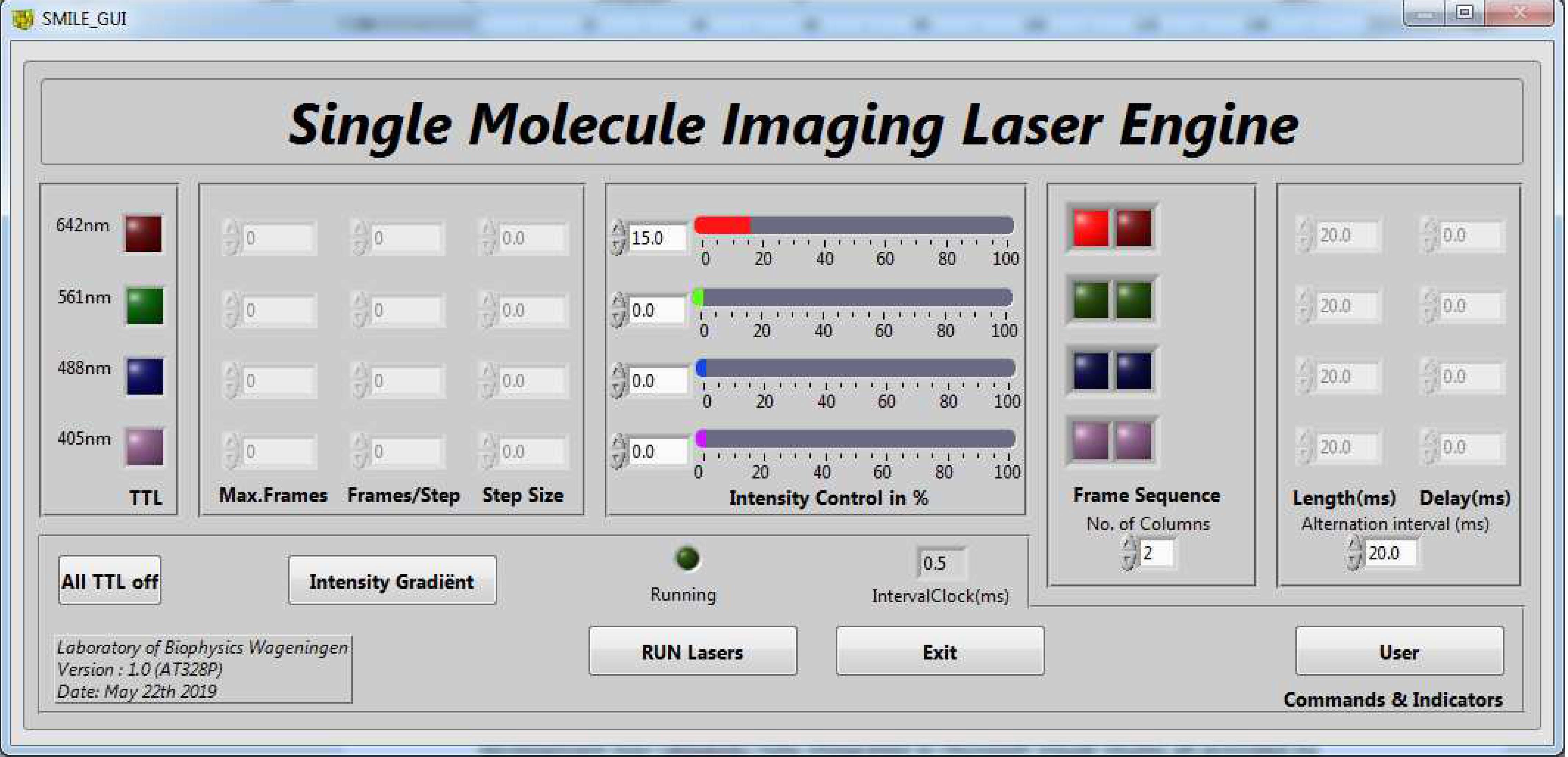
From left to right: To manual switch the lasers on and off, there are four buttons in the TTL window. With the All TTL off button you are able to switch off all lasers in one instance.
Pushing the (linear) Intensity Gradient button you are able to access the corresponding window. Thereby one can enter the Maximum amount Frames to stop the ramp. The amount of frames a step in intensity occur and at last the intensity step itself. The Intensity Control slider acts as an offset in the intensity ramp.
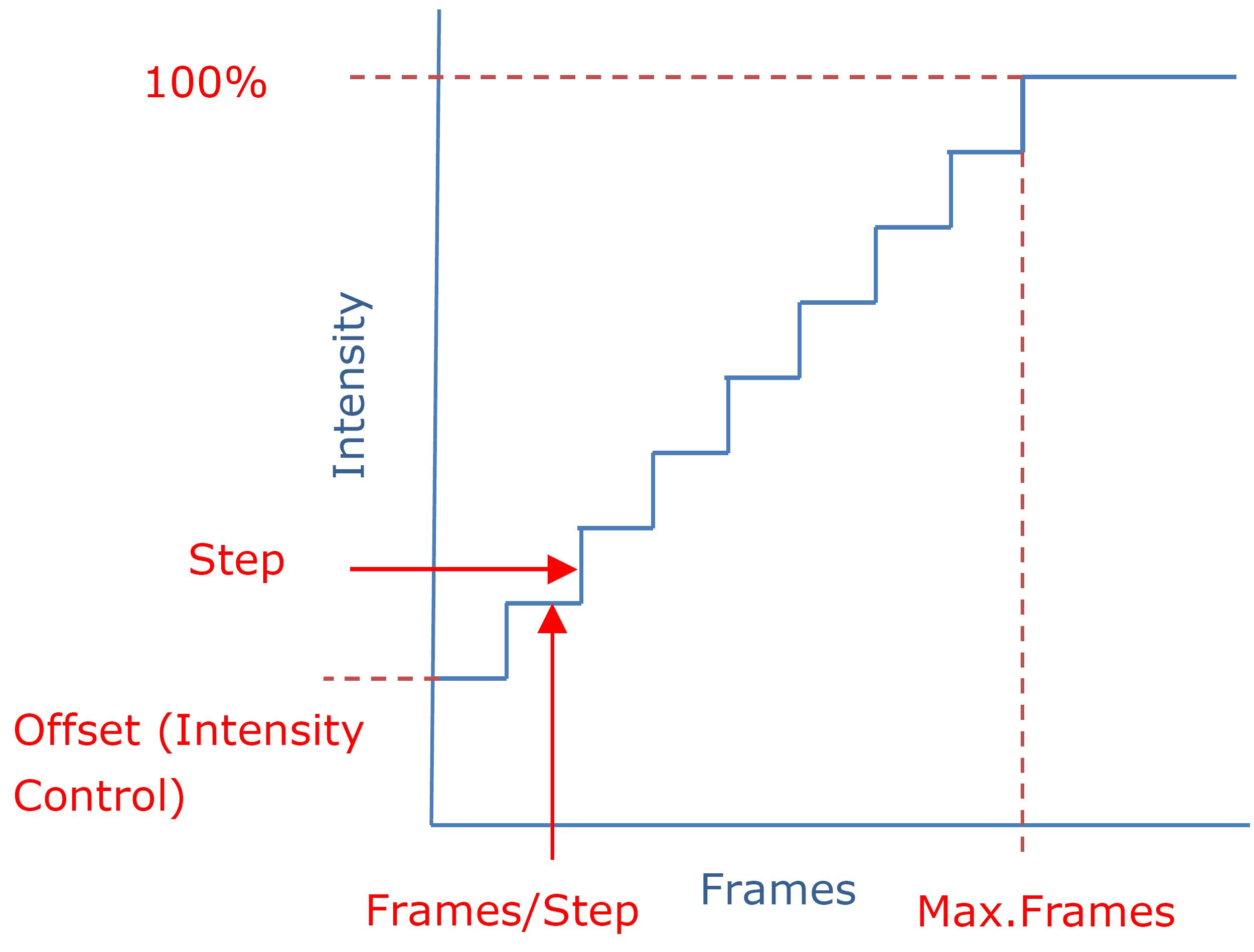
The maximum amount of frames is limited to 65535 ± 1. The (intensity) step is limited to the max. 100% ± 0.1% minus the offset ( Intensity Control). Note: in running mode all the ramping parameters including the Intensity Control are not accessible.
The Intensity Control slider controls the intensity to a maximum of 100%± 0.1% laser output power in both manual and running mode. In the Frame sequence you can control the frame pattern of Alternating Laser Excitation per laser. The frame sequence pattern can be set to the maximum of 4 (default 2).
The alternation interval is default 50 msec. but can be set as low as 2.0 msec. to maximum of 200 msec ± 0.5 msec. Default is SMILE in User mode. Click on the User button you'll enter the SuperUser mode. In SuperUser mode you are able to change the pulse length per laser colour and the pulse delay in respect to camera trigger. Note: by choosing a pulse length shorter than Alternation interval you create a post or trailing delay.
Technical Manual
The project consists out of a controller based on Arduino NANO hardware platform and a tailor made shield as a Digital Analogue Converter/driver. The software for the NANO is written in C language and is main task is listening to the USB port commands coming from the Graphical User Interface and translates them in hardware related commands. The GUI design/layout originates from previous SMILE GUI and its main purpose is to create a self-guided workflow which one would expect in an Alternating Laser Excitation experiment.The Graphical User Interface
The GUI is written in Labview merely for the use of its ready to use knops, sliders etc. The Labview Virtual Instrument is compiled in a Win64b executable called SMILE. As usual every knop of slider is event driven. For an event that causes to communicate with the laser controller there is also a call back to secure event was handled in the minimum of time. So in this case within GUI VI there are two processes one to catch the events and send them to the underlying process. The underlying process does the calculations, conditioning and transmitting data using the Arduino NANO communication driver.Controller hardware
The controller is based on the Arduino NANO hardware or better the ATMEL 328P microprocessor. The AT328P has in this case four useful components for this controller. Meaning a timer unit, UART, at least 9 digital outputs and a Serial Peripheral Interface. The timer unit is setup for the timer tick (500 μs) and originates from the (14 Mhz) resonator of NANO hardware. The UART is connected to a USB to serial converter operating on 57600 baud,8,1,N. The digital outputs operated as a set of 4 by 2. Meaning four outputs are used for switching off and on the analogue outputs. The other four outputs controlling the enable 12bit SPI DACs. The last output is used for the camera sync. pulse. Both analogue and digital operating between 0 and 5Vdc. So all the additional hardware is captured in a shield including external (9 Vdc) polarity protected power inlet. The power inlet was necessary especially for the 5Vdc DAC reference. Using the USB input voltage was too low for a full scale laser output, due to the Arduino +5V auto selector.Arduino NANO Software
The main reason to design in the NANO is not only the price but also the GNU based development tool (WinAVR) that is fully integrated in Microsoft Visual Studio all provided by Atmel (AtmelStudio). The software is written in C mainly for efficiency and portability. All hardware related code is sub divided in laser.c, spi.c, timer.c and uart.c. The laser.c part includes functions to initialise and control the laser IO as well the camera IO. SPI.c part includes functions to initialise and sending data over the Serial Peripheral Interface Timer.c includes the function to initialise the timer hardware. Uart.c includes the function to initialise the UART hardware as well sending and receiving data. Although sending was only used for debugging. Main.c is traditionally master control and is far most the biggest part of the assembly. Not in terms of assignment of variables needed but in functions to decoding the (command) telegram from the GUI and respond efficient enough not to interfere with the timing. The biggest and complex function is control the lasers. The function is written in a way that there is no limit to the amount of lasers. The only limit is the hardware in respect to IO and memory. The code for controlling the lasers are synchronised by using a non-interruptible timer of 500 μs. Both camera and laser control are in the same process cycle to keep jitter to a minimum. In running mode, using the camera out as trigger, jitter is less than 1 μs. There is only one exception and that is during communication between GUI and the laser control software. Because serial communication is asynchrony to laser control timing changing intensity in laser running mode would, in worse case, effect the laser timing. To minimise this effect, communication both USB/UART and SPI, is only allowed in odd frame (lasers are off) and keep the telegram as short a possible under the maximum reliable communication speed. To wrap things up, the laser control software uses 2144 bytes of Program Memory and 39 bytes of Data Memory of the Arduino NANO AT386P Micro Computer.Communication protocol
The AT328P its UART is setup for 57600 baud,8,1,N serial connection. The Arduino NANO driver is automatic select the correct baud rate. All the communication between de GUI and de laser controller is based on a two byte telegram captures in main.c by the structure name Telegram. The telegram start with a 4 bit laser color followed by a 4 bit command and a 2 byte data field. Meaning based on this telegram, 15 lasers can be called at, 15 commands can be addressed , accompanied by a unsigned integer (65535) for data.Commands
In the SMILE project the uses 12 to the 15 commands and captured in the enumeration called commands e.g. MODE = 1, STATUS, SEQUENCE, COLUMNS, ALTER, DELAY, INTENS, FRAMES, STEP, SFRAME, FRAMET, RESET.| Nr | Name | Action | Type | Data | Range |
|---|---|---|---|---|---|
| 1 | MODE | Manual/Run operation | boolean | dc | 0..1 |
| 2 | STATUS | Laser on/off, only manual | boolean | dc | 0..1 |
| 3 | SEQUENCE | reading Frame Sequence | uint8 | 1 byte | 1..255 |
| 4 | COLUMNS | Frame Sequence Columns | uint8 | 1 byte | 1..255 |
| 5 | ALTER | reading Alternation Interval Time | uint16 | 2 bytes | 1..400 |
| 6 | DELAY | reading Pulse Delay | uint16 | 2 bytes | 0..400 |
| 7 | INTENS | reading laser intensity | uint16 | 2 bytes | 0..4096 |
| 8 | FRAMES | reading max. frames (int.grad.) | uint16 | 2 bytes | 1..65535 |
| 9 | STEP | reading step (int.grad.) | uint16 | 2 bytes | 0..4096 |
| 10 | SFRAME | reading steps/frame (int.grad.) | uint16 | 2 bytes | 0..65535 |
| 11 | FRAMET | Alt. Interv. Time, Interv. ÷ Clock interv. | uint16 | 2 bytes | 1..400 |
| 12 | RESET | reset internal variables to default | boolean | dc | 0..1 |